Overview
Electrical System Overview
Harnessing & Electrical System Overview
At the core of our electrical system, we use an Arduino Uno and an Adafruit Motor Shield v2 placed directly on top of the Arduino to drive all hardware and firmware. The Motor shield has the capacity to drive up to 4 DC motors or two stepper motors, so for our product, it was the perfect amount since we needed one stepper motor and one DC motor.
On top of the motors, we also needed to use buttons with pull up resistors (debounce was handled in firmware) Here is a schematic diagram that was used to keep track of all the harnessing and wiring for the auto dealer. It also lists on the right hand side the different pins used and the corresponding wiring for it.
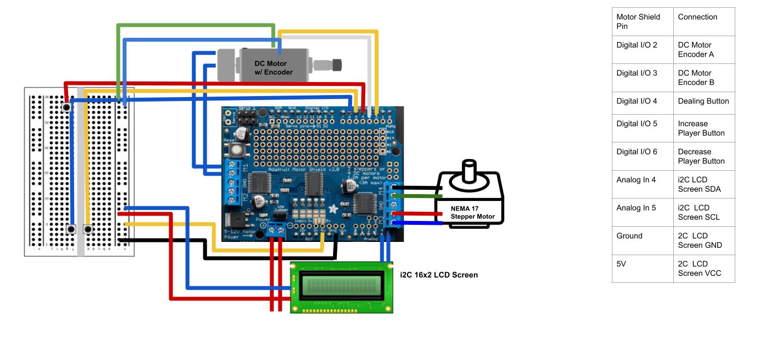
A schematic diagram of our electrical system
This is integrated into the actual card dealer, with the arduino, motor shield, and breadboard living right under the card dealer and on the pan mechanism. Note that Digital I/O pins are used only for the encoder and the three different buttons, while the LCD screen uses Analog pins for the i2C protocol.
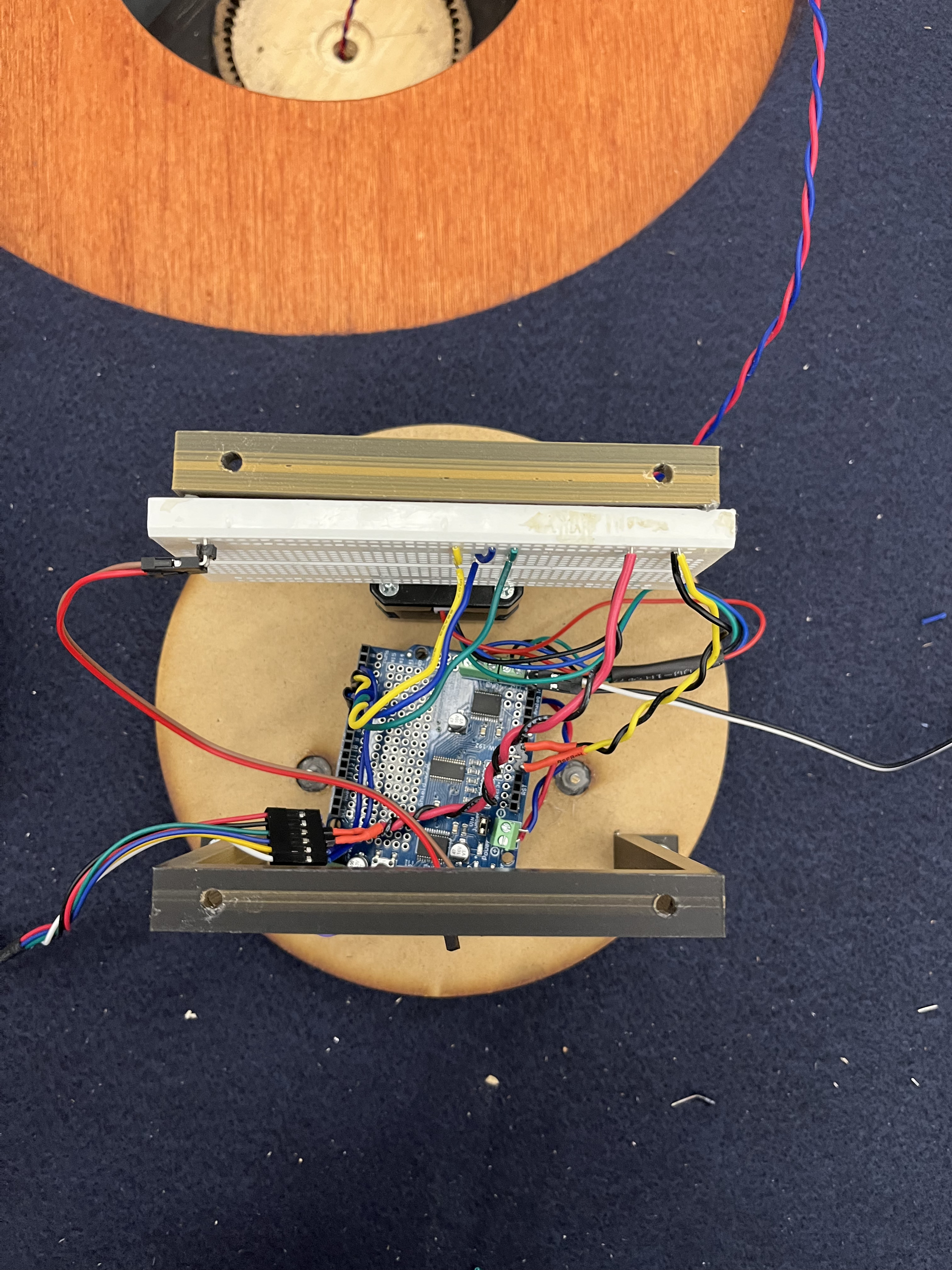
A topview of our integrated electrical system
The buttons and LCD Screen are embedded into the shroud, with wires soldered onto the buttons. The Arduino and the motor shield is powered through a AC power supply that is directly connected to the motor shield. The wires connecting the AC power supply to the Arduino go through a hole into the central column.
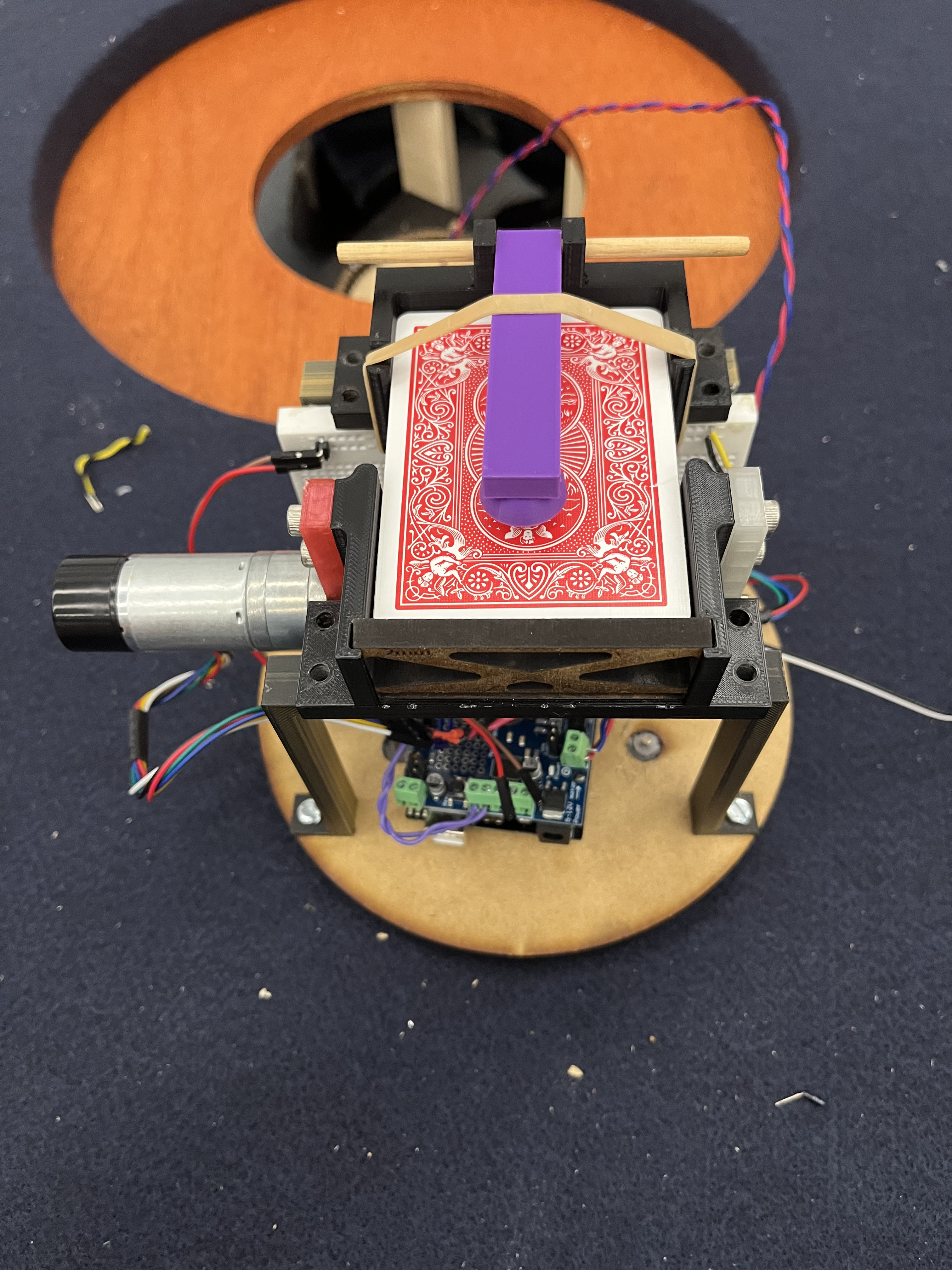
All electrical harnessing integrated
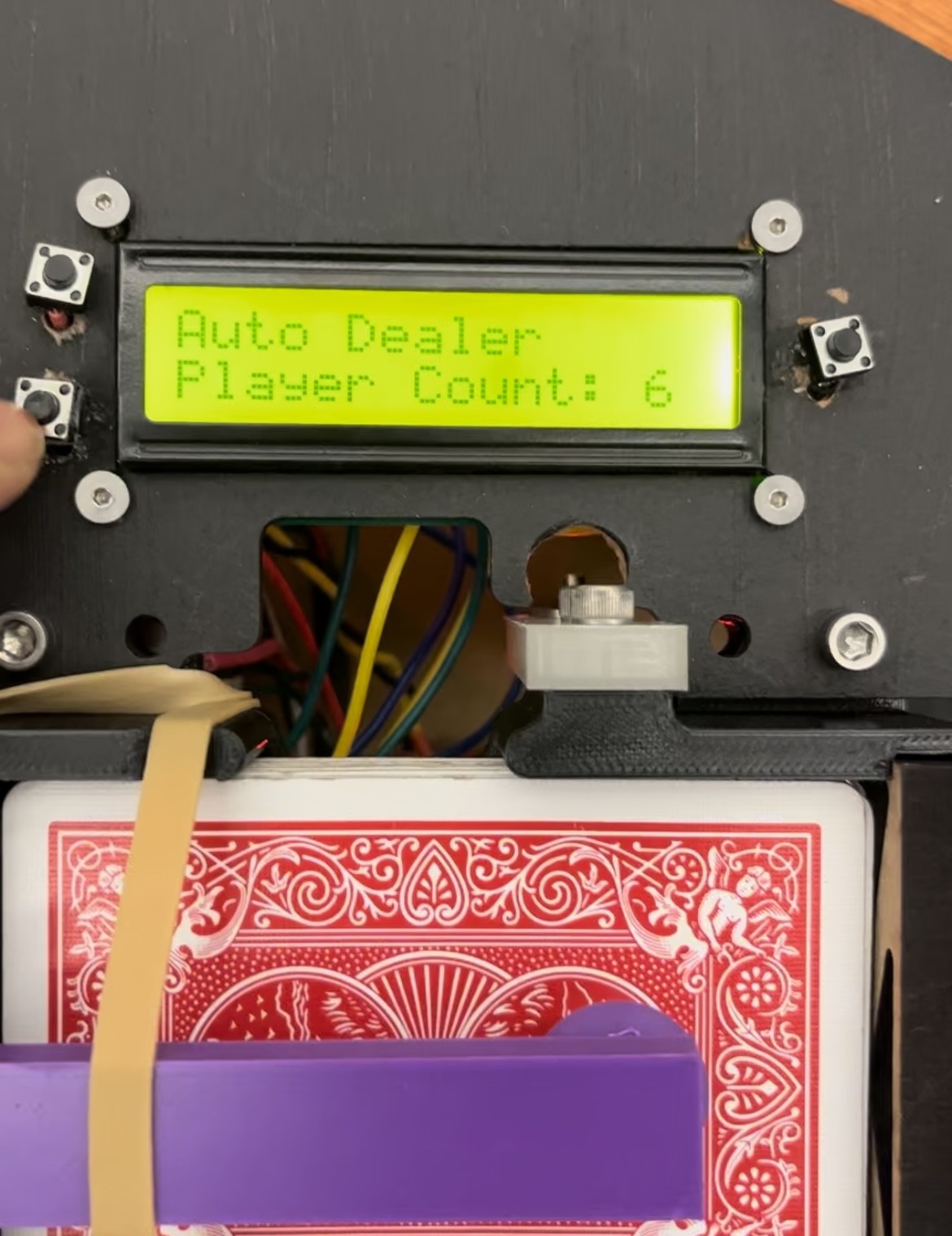
The LCD & buttons embedded into the shroud
The three buttons next to the LCD control the number of players and trigger dealing. The LCD is an 16x2 using an i2C protocol driver to simplify wiring with a serial Clock pin (SCL) and serial data pin (SDA) that handles all updates for the LCD Screen. The arduino Uno pins for i2C pins are Analog pins A4 and A5, as shown connected in the schematic diagram above.
One of the major goals in electrical was organization and longevity. Due to the numerous times when disassembly was required during integration and debugging, making sure that it was easy to know which wires went where was key, meaning that a clean harnessing so that it could all fit under the narrow space between the pan mechanism and the card dealer was crucial. Furthermore, the longevity of the system was critical since replacing wires once integrated was very difficult. Thus, we had to make sure that wires wouldn’t accidentally come out or short together and ruin the entire system. To keep the harnessing clean and prevent any shorts, we soldered almost all the wires to male headers and used heatshrink to prevent shorting. We also braided wires and color-coded wires as much as possible to make it easy to keep track of wires.
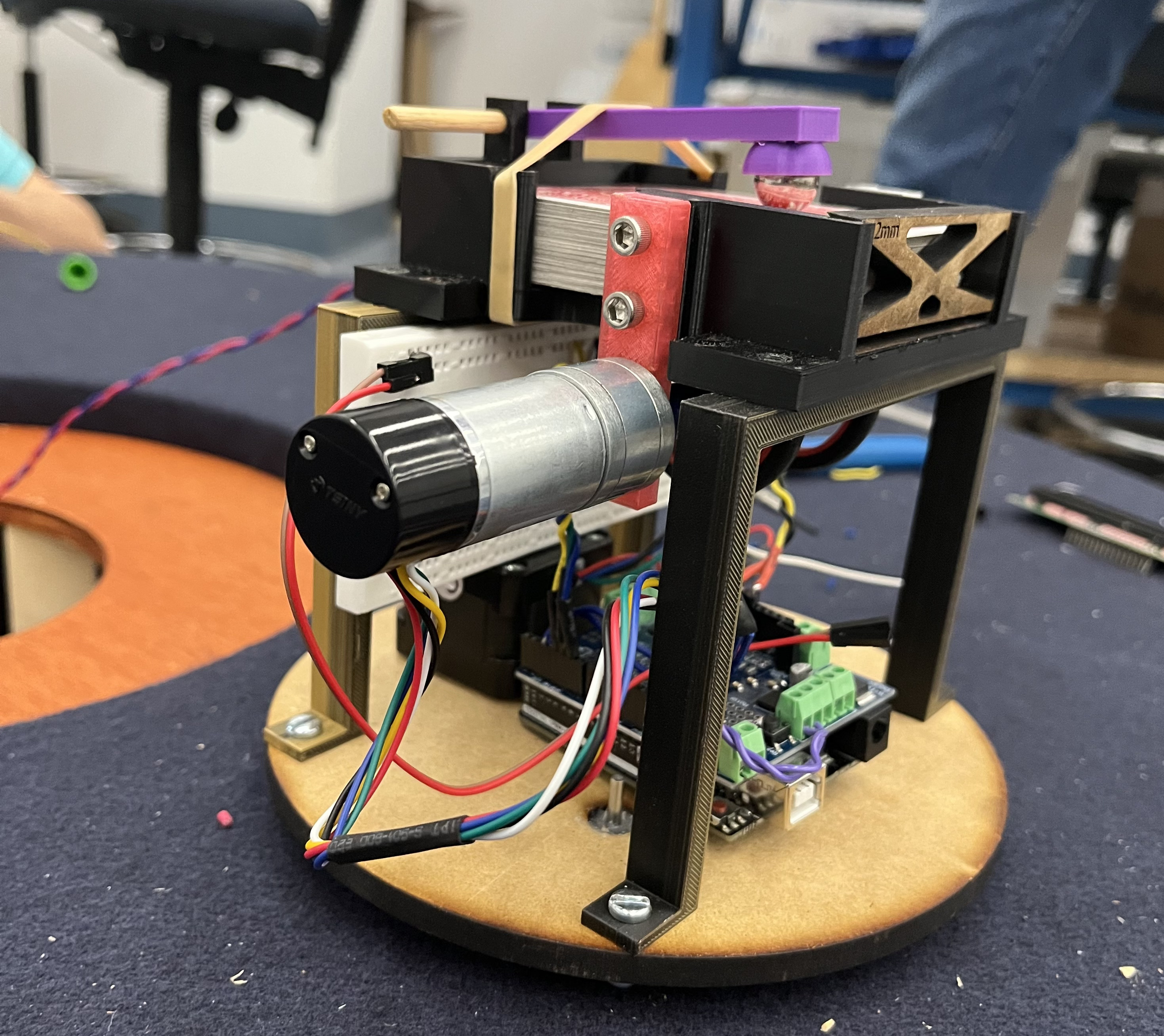
Final Electrical Integration (Sans Shroud)