Sprints
Sprint Three
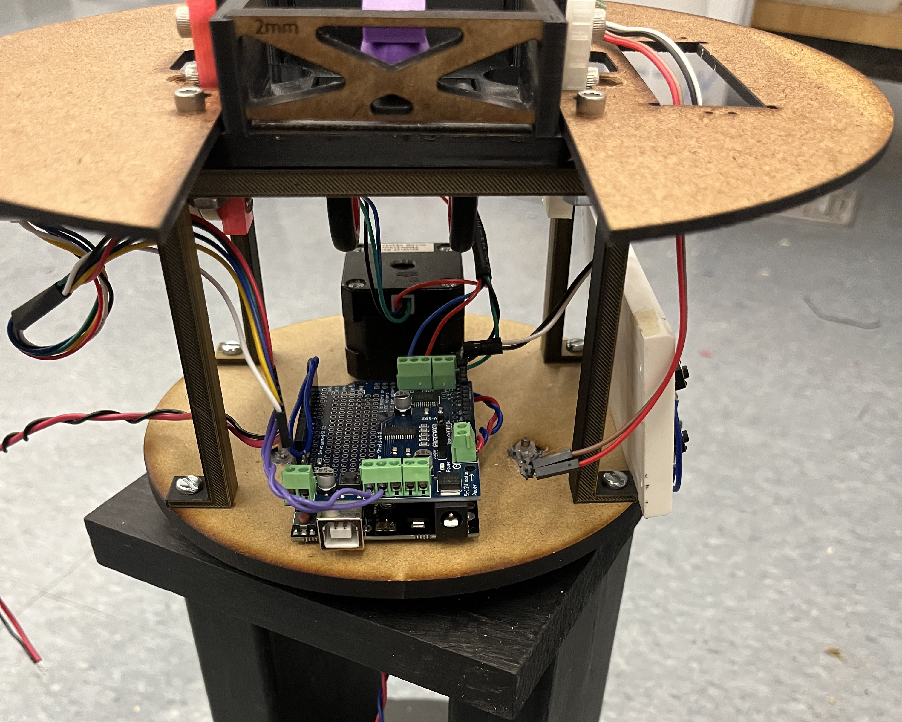
This sprint we completed all parallel reach goals and began electrical integration. For the first time, both DC motor, stepper motor, and LCD screen (with accompanying buttons) were wired onto the same Arduino and Motor shield. The past sprints all these components were tested and developed in isolation, and this was the first time we integrated everything together. Furthermore, this was the first time in firmware where all the different component’s associated firmware would be placed in a single sketch. Due to good coding practices, testing setups in firmware for debugging, and a schematic diagram for wiring, it made the integration process painless.
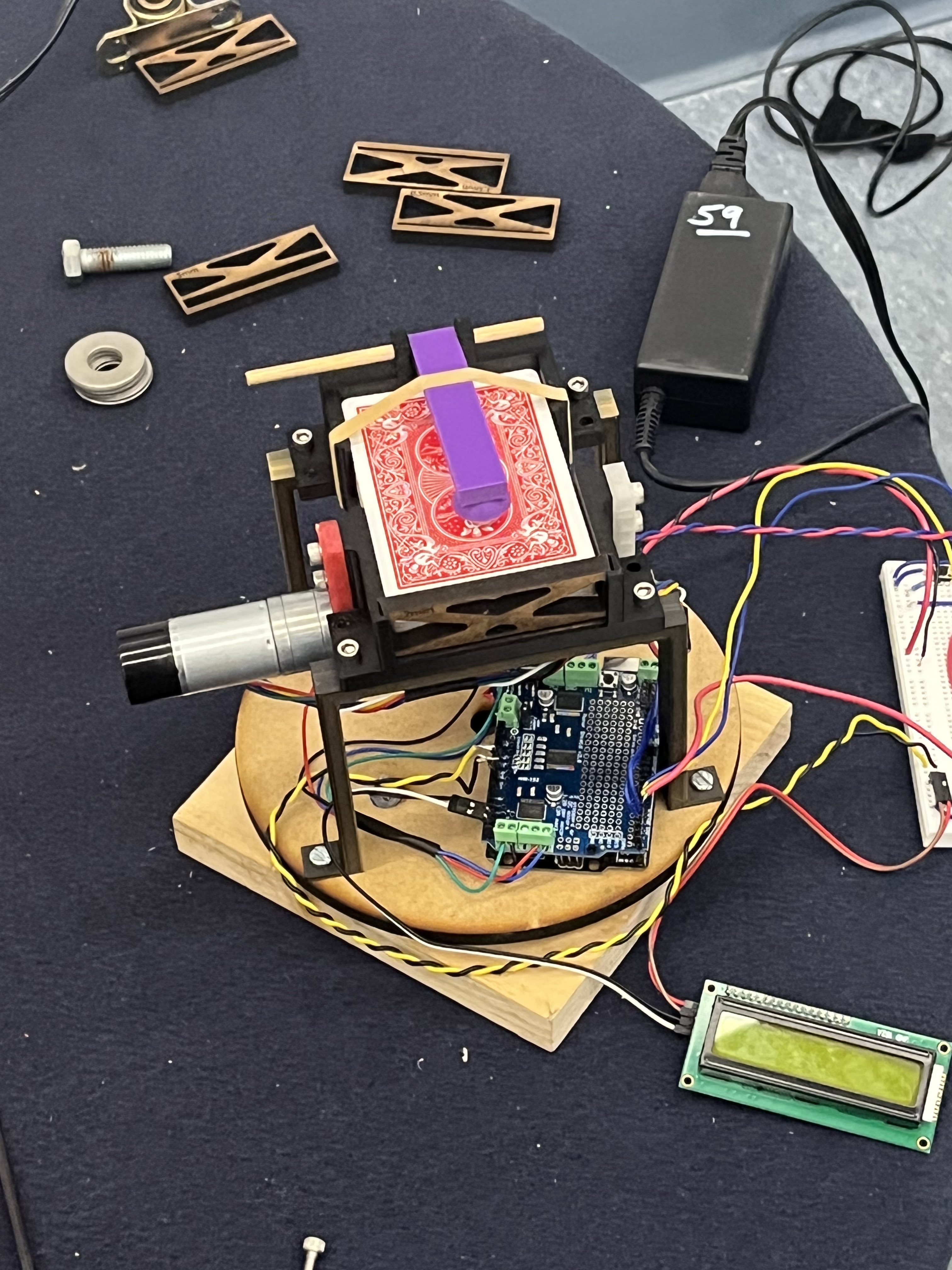
Full electrical integration.
Card Dealer
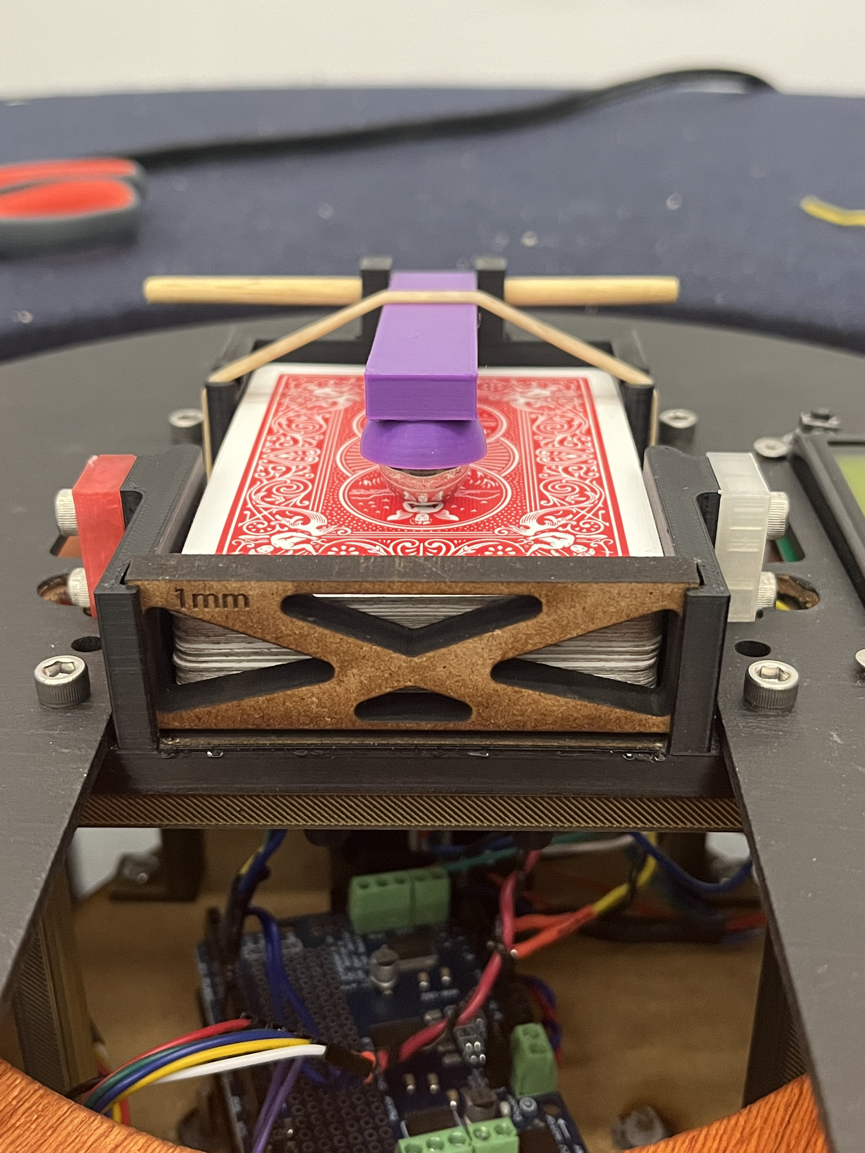
We upgraded our DC motor by using a new DC motor with an encoder during this sprint. This gave us finer control over dealing cards, allowing us to tune how much the motor spun to consistently deal one card. We found that the gate with a 1mm gap allows for cards to smoothly eject from the deck holder while preventing a second card from also slipping out. We also realized that the placement of the rubber band on the weight arm had a large impact on how consistently cards were dealt, as it would affect how much weight was actually being applied over the roller. Because of this, the final version of the deck holder has a slot that the rubber band fits into, allowing a user to consistently place the rubber band anytime they might move it (for example, when placing/removing a deck from the deck holder). Furthermore, during our testing, we took into account user experience design and added fingerholes to the card dealer which would allow users to easily take out cards.
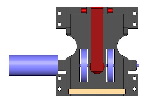
Final CAD of card dealer.
Table
We finished manufacturing the table and assembling it during this sprint as well.
The design of felt on a circular table presented a unique construction challenge, as making circular designs into wood is always difficult. After doing some testing, it was found that the maximum diameter of the table would ideally be 44 inches in order for everyone to be able to reach their cards. In fabricating the circular shape, the Shop Bot CNC Mill was used to cut out concentric circles that were used in the table top, supports, and footers. These were then screwed together to form a solid top with a lip around the bottom where felt could be stretched taut and stapled.
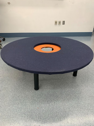
The final table design was assembled and integrated with the mechanical and electrical systems. Along with a nice felt top, the team wanted a nicer surface for the cards to fall upon, and thus a piece of plywood was coated with a cherry cerise finish in order to lend it a dark, red hue that contrasted well with the blue felt that was chosen for the table color. After the table top was assembled, the centerpiece was attached, and the felt was stretched taut across the surface, 14in legs were attached to the bottom, making a nice end table look that is sleek, practical, and works for all players.
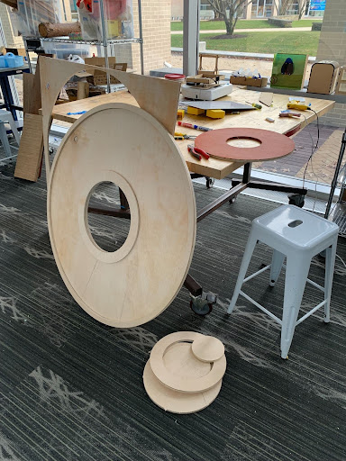
Table top parts from Plywood.
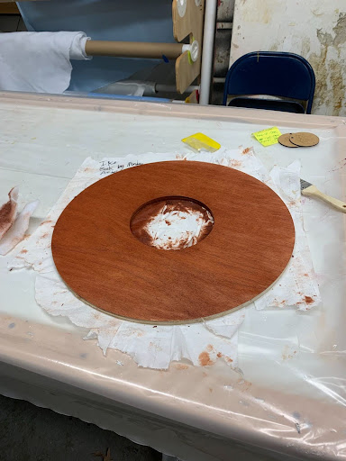
Cherry cerise finish for the table
Completed (unintegrated) table
At the end of our third sprint, this was our deliverable:
The Final Week
We had one week left before the Final Expo, in which we worked to completely integrate everything. During integration with the electrical components (i.e Arduino and Breadboard) in Sprint Three, we quickly realized that the chosen location between the dealer and the panning mechanism was too small for easy electrical integration. After communication between electrical and mechanical, we elongated the shooter legs to allow for easier access during integration and a perfect place to secure the breadboard. This way, the only wires that would be turning would be the power supply wire that was through the central column.
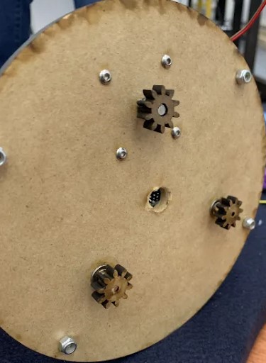
Final Improved Panning Mechanism with support gears
Shooter legs elongated
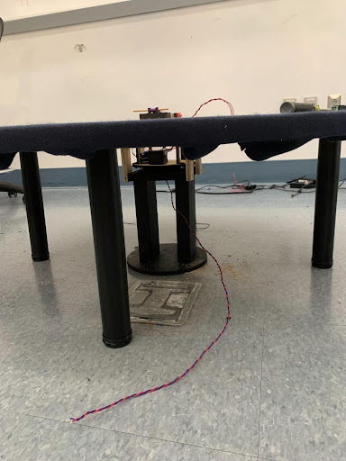
We also developed a central column where the card dealer and panning mechanism would rest on at the middle of the table. To blend into the table aesthetically as well as match the 3D filament we printed everything on, we painted it black. Taking into considerations the electrical requirements of a central hole for the power supply, the central column has two legs with a hole in the middle for the wires.
Shroud & LCD Screen
In our goal to make our auto dealer’s integration into the table as clean as possible, we also finished the shroud to cover all the electrical and mechanical workings. We began in CAD and eventually laser printed the shroud before painting it to match the central column. We also embedded the LCD Screen and wires into the shroud.
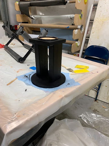
Picture of central support column.
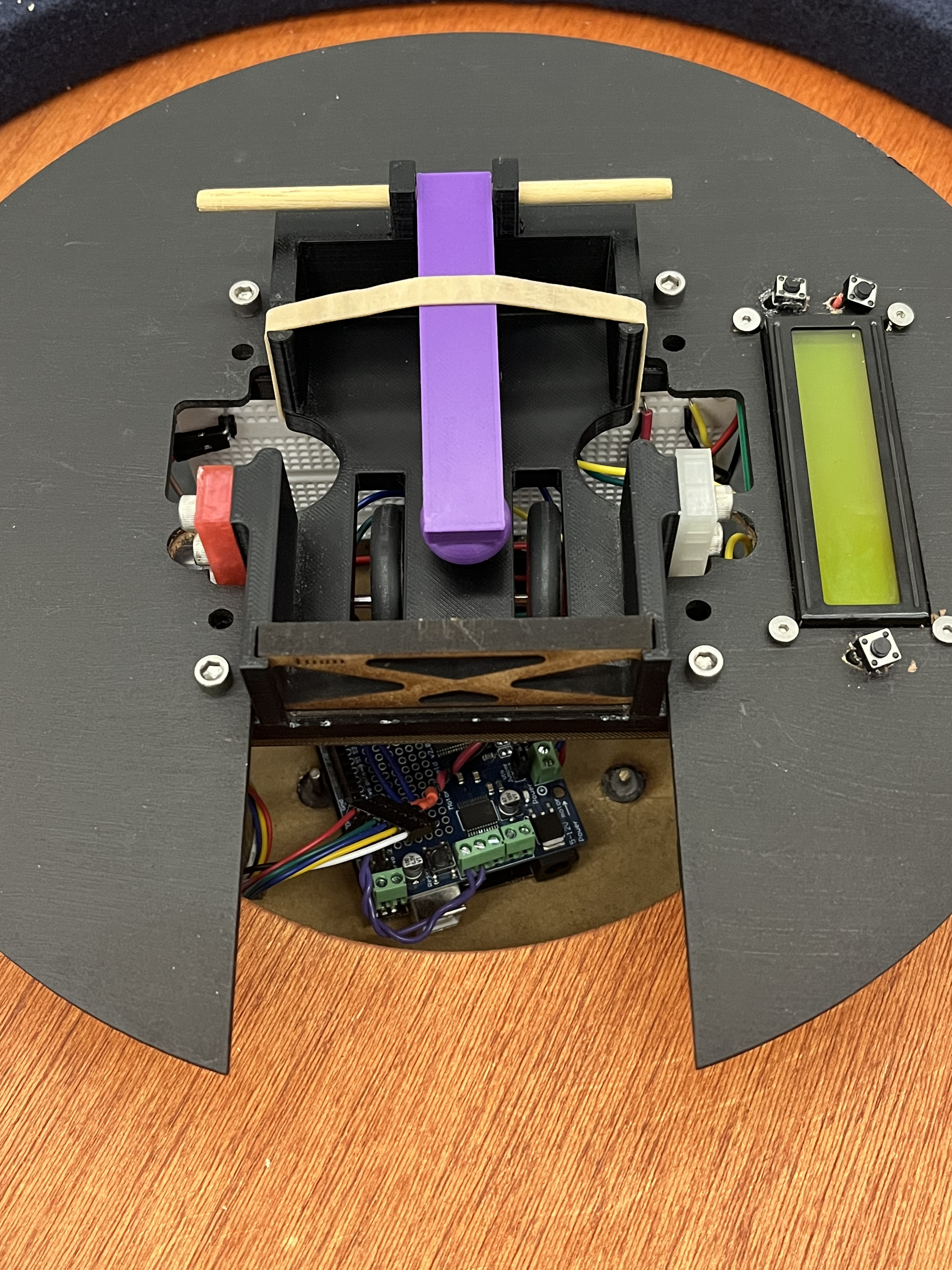
Shroud Integration with LCD Screen, Buttons, and Card Dealer
Card Dealer, Shroud, and Panning Mechanism integrated into central column
Table
Once the table was built, then it had to be integrated with the card dealer. For this to be done there had to be a central column on which the card dealer could sit upon. This was fairly easy to build and fit comfortably and securely under the table, attached to the rest of the table through four arms. Finally,the felt was cleaned and paint was added to every visible surface to make the final product look nice and well integrated.
Full Integration
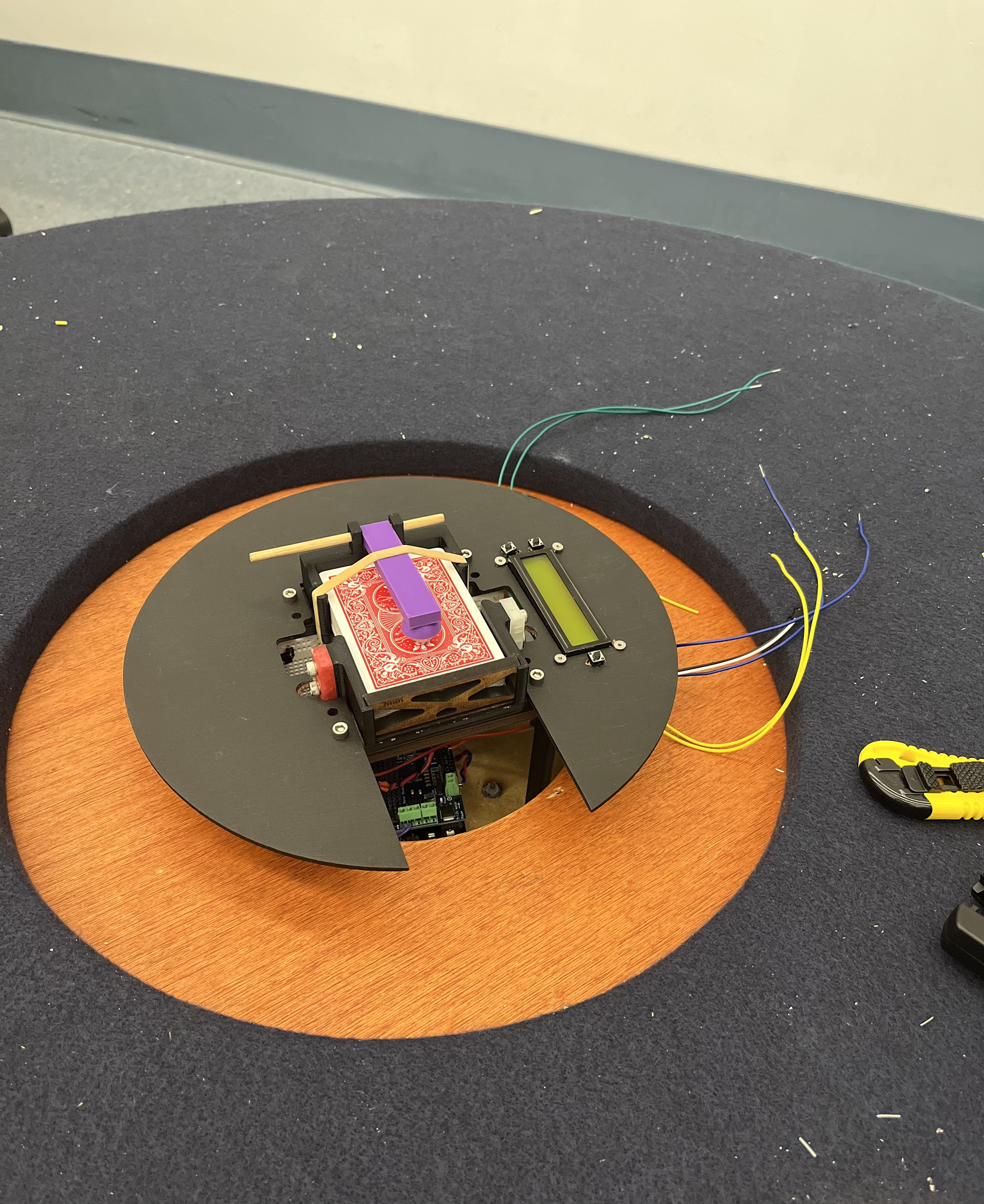
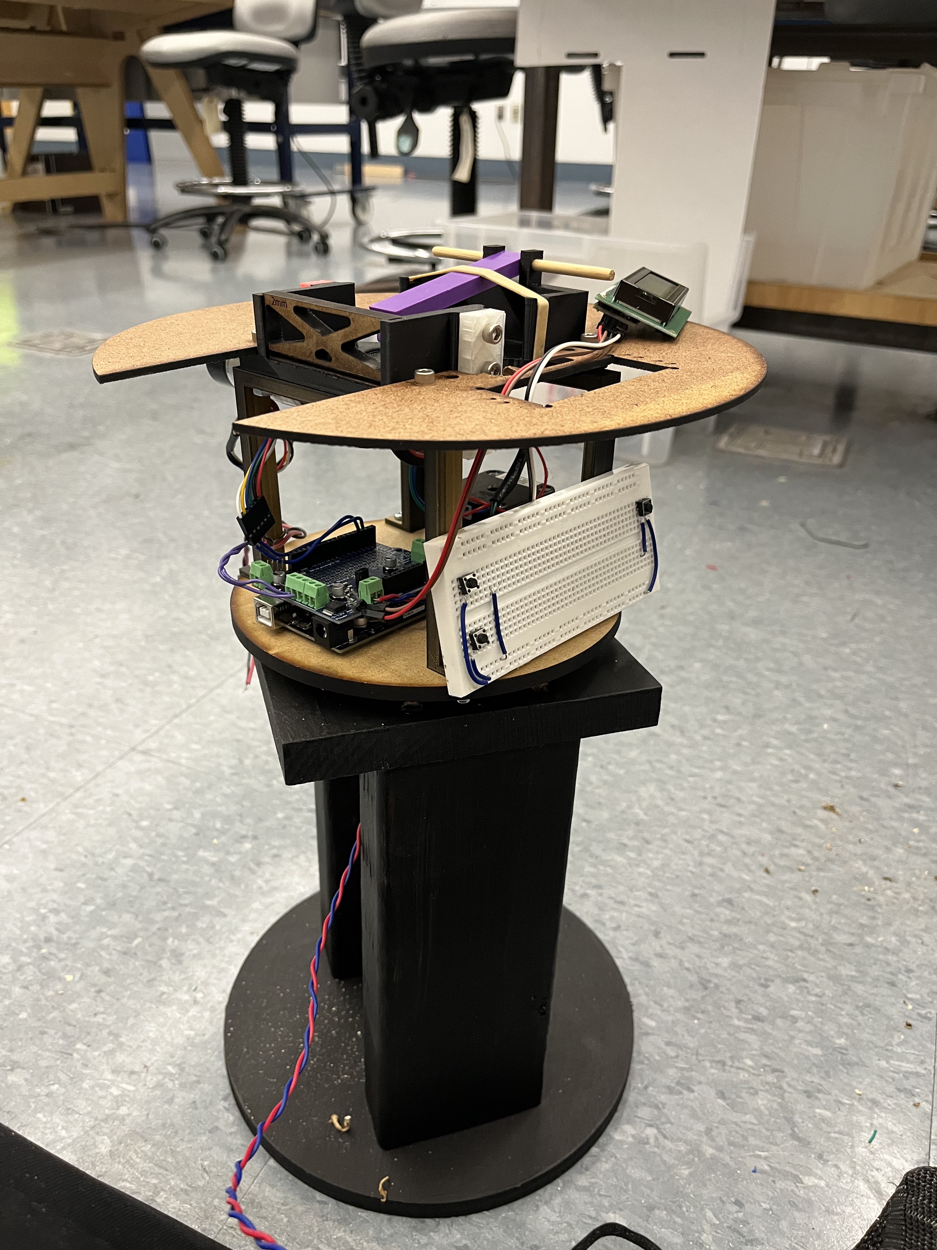
Final Integration of all components.
Closeup of card dealer after final design and integration with shroud
Side view off complete integration
Thus, our very final product at the end was a aesthetically clean card dealer integrated into a table with a modular number of players.